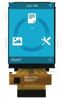
DT022BTFT
2.2" Color TFT LCD Display
Request a Quote
240 x 320 2.2" TFT Display
DT022BTFT is a display module that contains a TFT display with a 320 x 240 RGB resolution. The driver used for this 2.2 inch LCD is the Ilitek ILI9341 (or compatible) and can display 262K colors. The driver is mounted on the glass and the interconnection via FPC including components to drive the display module.
Technical Overview
| Diagonal Screen Size | 2.2 inch |
| Display Resolution | 240 (RGB) x 320 |
| Viewing Angle | 6 o'clock |
| Interface Type | MCU Parallel, RGB, or SPI |
| Brightness | 200 cd/m2 |
| LCD Driver IC | Ilitek ILI9341 |
| Module Size (w x h) | 41.7 x 56.16 mm |
| Active Area (w x h) | 33.84 x 45.12 mm |
| Pixel Size | 0.141 x 0.141 mm |
| Operating Temperature | -20 ~ 70°C |
Datasheets
Support Documents
Technical Support Notes
Connections from MCU to Display
The DT022BTFT uses the same connections as the DT022CTFT, with the exception of the backlight (which has connections shown in the Displaytech datasheet).
Sample Code
The provided display driver example code is designed to work with Microchip, however it is generic enough to work with other micro-controllers. The code includes display reset sequence, initialization and example PutPixel() function. Keep the default values for all registers in the ILI9341, unless changed by the example code provided.
SPI Interfaces
3-line Serial Interface
See ILI9341 datasheet sections 7.1.8-7.1.10, 7.6.1 and 19.3.3
4-line Serial Interface
See ILI9341 datasheet sections 7.1.8-7.1.10, 7.6.2 and 19.3.4
4-Wire 8-bit Serial Data Interface II
4-wire 8-bit Serial Data Interface II is the correct mode to use based on the microprocessor pins available. This mode is closest to standard SPI port operation with a few minor exceptions.
Please review the ILI9341 driver IC datasheet:
- Page 33, paragraph 7.1.8 describes the serial interface timing for the SPI pins
- Page 35 has a useful timing diagram for the 4-line Serial Interface Protocol
Note that the WR pin becomes the D/CX signal in serial mode. CS is used to initiate a data transfer by pulling it low. At the end of the data transfer, pull the CS pin high to complete the transaction. The timing diagram indicates that you can pull the CS pin high in between the command byte and data bytes within a transfer, but it is unlikely needed if the display is the only device on the SPI bus. To keep things simple, we suggest to leave it low during the entire transaction.
The D/CX pin tells the ILI9341 that the current byte is either command or data. Pull the D/CX pin low when the current byte is a command, and pull high when it is data. The timing diagram indicates only needing to set D/CX on the last bit of a byte, but it is much simpler to just leave it high or low during the entire byte.
Here are the pin connections needed:
| Pin | Symbol | Display Connections |
| 2 | IMO | GND |
| 3 | IM1 | +3volts VCC |
| 4 | IM2 | +3volts VCC |
| 5 | IM3 | +3volts VCC |
| 6 | Reset | Resets ILI9341. Pull low momentarily after power-on to reset chip. |
| 7 - 28 | GND | |
| 29 | SDO | 4 wire MISO (SPI master input) |
| 30 | SDI | 4 wire MOSI (SPI master output) |
| 31 | RD | GND |
| 32 | SCL | 4 wire spi SCK |
| 33 | WR | 4 wire spi DC/X (Pull low for command byte; high for data byte) |
| 34 | CS | 4 wire spi chip select. Pull low to start a data transaction. Pull high when transaction is finished. |
| 35 | FMARK | Not connected |
| 37 | GND | GND |
| 38 | LEDA | +5 volts |
| 39 | LEDK1 | 120 ohm to GND |
| 40 | LEDK2 | 120 ohm to GND |
| 41 | LEDK3 | 120 ohm to GND |
| 42 - 45 | NC | Not Connected |
It is best to use PWM for backlight control. For prototyping, the LED backlight anode pin needs to be driven by a 5 Volt supply and each individual LED cathode needs a current limiting resistor. You can use a lower anode voltage than 5V, but you will need to calculate a new resistor value. The backlight LED voltage drop is about 3.2 Volts and varies with temperature.